
EARTHING AND BONDING
What is Earthing?
The purpose of earthing is to reduce the danger of electric shock and the risk of fire, due to earth fault conditions.
The fault current is directed to the general mass of earth, and a protective device (such as a circuit breaker or RCD) will operate, causing the faulty circuit to disconnect.
Without adequate earthing arrangements, the protective device would not operate within the required time to prevent serious harm from electric shock or damage from fire.
Earthing Systems
There are various types of earthing systems, but the most common ones are TN-C-S, TN-S or TT:
TN-C-S –
Terra Neutral-Combined-Separated
Also known as PME, this is the most common form of earthing arrangement used in the United Kingdom as it provides a low voltage supply with reliable and safe earthing via a combined earth/neutral conductor. The connection to earth is provided via the Distribution Network Operator’s supply cable.
Although this is most effective form of earthing the installation, there are certain circumstances where an alternative earthing arrangement may be needed, such as EV supply equipment (car chargers), swimming pools, hot-tubs and agricultural premises.
The main drawback of a TN-C-S arrangement is if the supply cable gets damaged and the combined earth/neutral conductor is broken. This can result in a voltage appearing on the exposed metalwork in your property, causing a risk of electric shock. In order to reduce this risk, there are strict requirements to provide adequate protective equipotential bonding to incoming services with metal pipework such as water, gas and oil.

TN-S –
Terra Neutral-Separated
In a TN-S system, the connection to earth is also provided by the Distribution Network Operator (DNO). The most common arrangement is a two-core cable (Live and Neutral) with earth provided by a lead outer sheath. The neutral and earth wires are separate throughout the supply cable.
The main advantage is that for underground supplies, the outer metal sheath is in direct contact with the ground for the whole length of the cable. This ensures the earth connection is at the same potential as the real earth.
However, the outer metal sheath can deteriorate over time until it is no longer an effective conductor. In the event of this happening, the DNO would be required to replace the supply cable, and it is likely that the earthing system would be upgraded to TN-C-S. As a result, TN-S systems are becoming less common.
You may not always be aware if the TN-S earthing arrangement in your property has been upgraded to a TN-C-S arrangement, therefore without confirmation from the DNO, the earthing and bonding requirements for TN-C-S systems should be applied.

TT
Terra Terra
In a TT earthing system, there is no electrical earth connection provided by the Distribution Network Operator. The earth connection is the responsibility of the property owner and is normally provided by a metal earth rod in the ground. This connection must be protected from corrosion and accidental damage or disconnection. It must also be accessible for testing and inspection purposes.
It is more commonly found in older and more remote or rural properties. There are also scenarios where parts of your installation are unable to be connected to the TNCS (PME) system, and an earth rod may be used in this instance too, for example EV supply equipment (car chargers), swimming pools, hot tubs, and detached outbuildings.
A disadvantage of a TT system is the length of rod required to provide a sufficient earth connection. A rod in excess of 1200mm is driven into the ground, avoiding any underground services such as service pipes, drainage or cables. However alternative methods are also available that alleviate the need for the use of rods, such as earth mats, earth tape, discs or similar.
The connection to earth is less effective than in a TN-C-S or T-N-S system, and therefore for protective devices to operate in sufficient time to minimise risk of serious electric shock, RCD protection is required for all circuits within the installation.


Earthing and Bonding Conductors:
These can usually be easily identified as they are coloured/sleeved green and yellow.
Main Earthing Conductor
The cable that connects your electrical installation to the general mass of earth via the Main Earthing Terminal.
Main Protective Bonding Conductors:
The cables that connect the incoming metalwork to the main earthing terminal.
Circuit Protective Conductors (CPCs):
The conductors that connect the final circuits within the installation to the main earthing terminal. These protect the cable as well as the equipment and accessories installed. The CPC should be run and terminated in every accessory on the circuit, and should not be cut off, even if not required (eg in class 2, insulated accessories).
Earthing and bonding conductors should be sized in accordance with BS7671 IET Wiring Regulations, in order to provide adequate protection against electrical shock and damage to your installation.
Main protective equipotential bonding:
Any metalwork that is in contact with earth and entering your property can introduce a different potential to the earth potential of the electrical installation. The most common examples of these are water, gas and oil pipes.
Main protective equipotential bonding connects the incoming metalwork to the main earthing terminal via a protective bonding conductor. This limits the difference in potential between two accessible conductive parts when an earth fault occurs, reducing the risk of electric shock. The bonding conductor should be sized according to the type of earthing arrangement in the property.
In older installations, it is likely that the incoming pipework will be metal. It is important to ensure that protective equipotential bonding has been installed, and if so, that the conductors are sized correctly. If additions or alterations are made to the installation, the requirements for main protective equipotential bonding should comply with the current edition of the BS7671 IET Wiring Regulations.
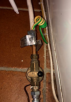
The bonding conductor should be secured to the incoming pipework, ideally within 600mm of where it enters the property. The connection should be made via a BS951 clamp and the termination of the conductor should be secure so that it cannot be inadvertently disconnected. The clamp should incorporate a notice stating “Safety Electrical Connection. Do Not Remove” and should remain accessible for inspection. Should you find that the conductor has become loose or disconnected, this should be rectified as a matter of urgency.


BS951 bonding clamps and warning label

Bonding to incoming water supply pipe
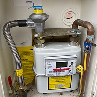
Bonding to incoming gas supply pipe
Bonding to incoming oil supply pipe
Typical locations of protective equipotential bonding:
Water – This would normally be adjacent to the stop tap and is often found under the kitchen sink. The connection should be made on the consumer side of the stop tap.
Gas - Adjacent to the meter.
Oil – In the proximity of the boiler.
If the incoming pipes are plastic (insulated), or they do not come in contact with the ground, a potential will not be introduced. Generally, these do not require bonding, however this should be confirmed by carrying out tests.


Examples of inadequate earthing and bonding:


If you have any concerns about the earthing and bonding arrangements at your property, please do not hesitate to contact us.